I. The Bottleneck of Traditional Cooling: Why Must We Shift to Liquid Cooling?
With the explosive growth of AI, high-performance computing, and cloud services, the Thermal Design Power (TDP) of server chips has rapidly climbed from tens of watts to hundreds or even thousands of watts. Traditional air cooling — relying on high-speed fans and dense heat sink fins — is approaching physical limits. Air cooling not only generates high noise and energy consumption but also struggles with heat dissipation per unit volume as data center rack density continues to increase. When a single rack exceeds 15kW, air cooling often falls short, leading to chip throttling, shortened equipment life, and high Power Usage Effectiveness (PUE).
Against this backdrop, liquid cooling solutions, leveraging their far superior specific heat capacity and thermal conductivity compared to air, have become the inevitable choice for addressing high heat density challenges. Within a liquid cooling system, the liquid cooling tube insertion process plays a critical role — akin to connecting blood vessels in the circulatory system. In fact, the safety, reliability, and maintainability of a liquid cooling system largely depend on the quality of the liquid cooling tube insertion process.
II. System Positioning and Core Functions of Liquid Cooling Tubes
Liquid cooling tubes (including hoses, rigid tubes, bellows, etc.) are the channels connecting cold plates, Coolant Distribution Units (CDUs), manifolds, and other key components. They deliver coolant precisely to the cold plates of each high-power chip and return the heated coolant to the CDU for secondary cooling.
Their specific functions include:
· Energy transport – ensuring low flow resistance and high flow rate of the coolant.
· Flexible connection – accommodating server node insertion/removal, rack vibration, and displacement due to thermal expansion/contraction.
· Leakage barrier – high-quality liquid cooling tubes and their connection structures are the first physical defense against coolant leakage.
III. Typical Characteristics and Material Selection Requirements for Liquid Cooling Tubes
To fulfill the above functions, server liquid cooling tubes generally possess the following characteristics:
Material compatibility – long-term resistance to coolants such as glycol-water solutions, deionized water, or fluorinated fluids without corrosion or particle shedding. Common materials include EPDM rubber, PFA/PTFE fluoroplastics, and 316L stainless steel.
Low outgassing & low ionic contamination – especially in immersion or single-phase liquid cooling, the inner wall of the tube should be extremely smooth to prevent microbial growth or particle blockage of cold plate microchannels.
Temperature and pressure resistance – operating temperature range typically covers -40°C to 150°C, with pressure resistance meeting design requirements of 1.0–1.6 MPa.
Flame retardancy and environmental compliance – meeting UL94 V-0 or higher flame rating and RoHS directives.
IV. Detailed Explanation of the Liquid Cooling Tube Insertion Process
The liquid cooling tube insertion process refers to a set of methods for quickly, sealingly, and repeatedly connecting liquid cooling tubes to blind-mate connectors (plug side) on server nodes, receptacles on rack manifolds, or distribution components. The standard process is as follows:
4.1 Preparation and Inspection Before Insertion
· Connector cleaning – ensure sealing surfaces of the male and female quick-connect couplings are free of debris and scratches. Wipe gently with a lint-free cloth dipped in a dedicated cleaning solvent.
· Seal pre-lubrication – some rubber O-rings require application of lubricant compatible with the coolant to reduce insertion resistance and extend seal life.
· Tube length verification – check the arc length and routing of the liquid cooling tube to avoid excessive tension or slack that could stress the connector.
4.2 Manual Insertion (for single node maintenance)
Pull the server node out to the service position.
Hold the male connector at the end of the liquid cooling tube with one hand, and secure the rack-side female connector with the other; align the guide keys or locating pins.
Apply vertical force to push the male connector into the female until a "click" locking sound is heard, and visually confirm the latch is fully closed.
Gently pull back on the tube to verify a firm, non-loose connection.
4.3 Blind-Mate Liquid Cooling Tube Insertion (for high-density racks)
In high‑density deployments, the server automatically completes the liquid cooling tube insertion as it is pushed into the rack — i.e., blind-mate connection. Key process points:
· Floating guide design – uses a 3D dynamic floating structure that allows the male connector to self‑align within a radial range of ±1.5 mm and angular range of ±2°, compensating for rack manufacturing tolerances and thermal deformation.
· Insertion force control – high‑quality blind‑mate connectors typically have an insertion/withdrawal force not exceeding 50N, preventing rack rail deformation or failure to fully seat.
· Keyed/meant-to-be-mistake-proofing – supply and return lines use connectors of different sizes or keyed slots to ensure correct liquid cooling tube insertion direction and eliminate cross‑connection.
4.4 Post-Insertion Seal Verification
After each liquid cooling tube insertion, leak detection must be performed. Common methods include:
· Pressure decay method – pressurize the fluid circuit with dry nitrogen to a set pressure, hold for 15–30 minutes, and observe whether the pressure drop is within the specified limit (e.g., ≤1%).
· Leak detection cable – connect a leak‑sensing cable along the tube; any trace of liquid contact triggers an alarm.
· Operational test – fill the system with coolant and circulate, visually inspecting all insertion points for wetness or crystallization.
Professional Practice
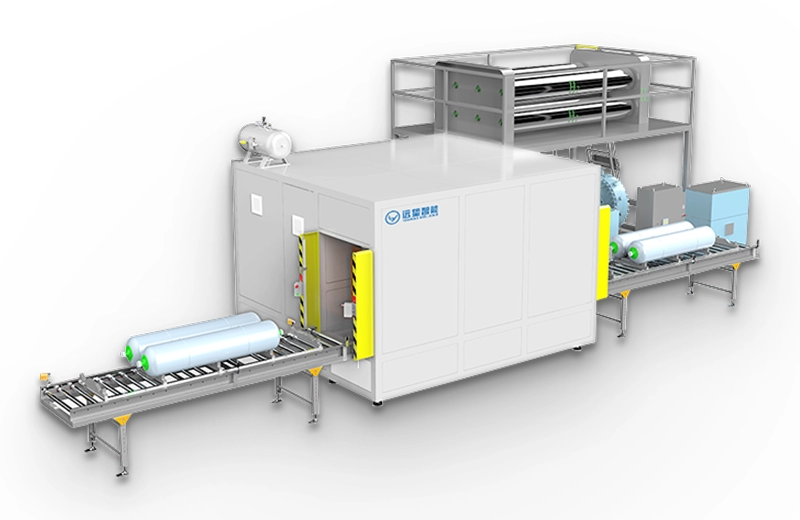
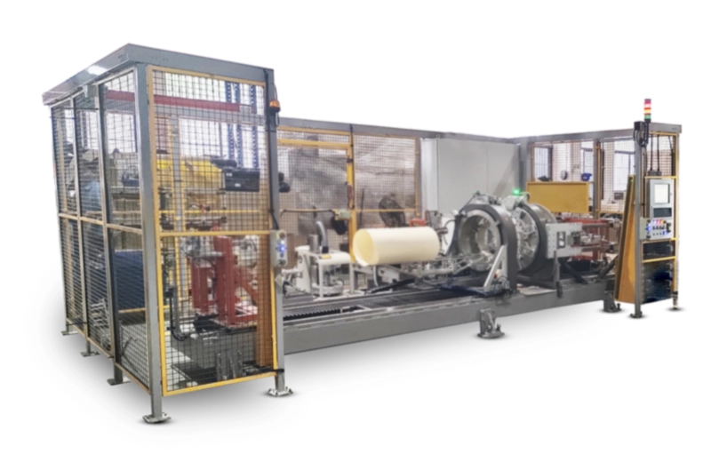
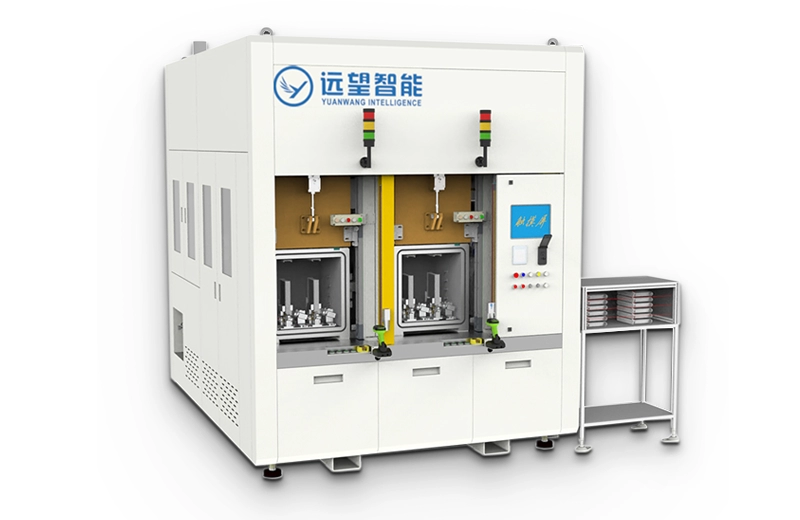
In volume production and data center deployments, the automation and standardization of the above liquid cooling tube insertion process are often undertaken by specialized equipment manufacturers. Shenzhen Yuanwang Industrial Automation Equipment Co., Ltd. (Yuanwang Intelligence) has deep technical expertise in the field of hose automation. The company has successfully developed automation systems covering key processes such as automatic hose feeding, precision cutting, and automatic assembly of hoses with various fittings. Notably, the hose materials it handles are softer than conventional server liquid cooling tubes, imposing even higher demands on feeding stability, cutting accuracy, and deformation control during assembly. This technical capability can be transferred to upstream steps of the liquid cooling tube insertion process — for example, length cutting of liquid cooling tubes and pre‑assembly of connectors — providing solid technical support for the automated production of liquid cooling components.
V. Common Risks and Countermeasures in the Insertion Process
VI. Conclusion
As data centers evolve toward racks of hundreds of kilowatts or even megawatts, liquid cooling has become a necessity. The reliability of the liquid cooling tube insertion process directly determines the safety and operational efficiency of the entire liquid cooling system. From material selection and insertion operations to seal verification and intelligent monitoring, only by standardizing and refining every liquid cooling tube insertion step can we achieve truly "zero‑leak, high‑density, and easy‑to‑maintain" liquid cooling systems. With the spread of UQD (Universal Quick Disconnect) 2.0 standards and blind‑mate floating technology, the liquid cooling tube insertion process will become even smarter, safer, and more efficient, providing a solid foundation for server thermal management in the high‑compute era.